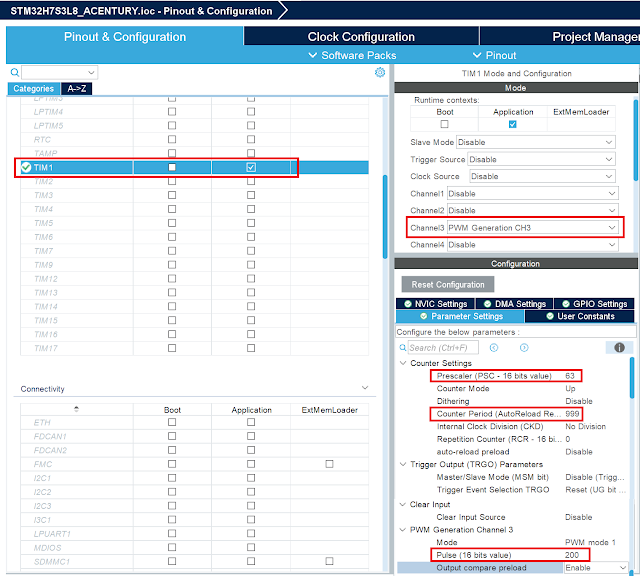
To configure Timer1 for a 1 kHz PWM signal with a 20% duty cycle on an STM32H7S3L8 microcontroller, follow these steps:
1. Understand the Timer Parameters
- PWM Frequency: 1 kHz → Period = 1 ms.
- Duty Cycle: 20% → ON time = 0.2 ms.
The timer’s clock frequency is derived from the APB clock (e.g., TIMCLK). Let’s assume you know the APB clock frequency. The Timer prescaler and auto-reload register (ARR) define the PWM frequency.
2. Compute Timer Parameters
Formula:
For 1 kHz PWM:
- Prescaler: Adjust it to reduce the timer clock to a manageable range.
- ARR: Defines the PWM period.
- CCR1 (Compare Register): Controls the duty cycle.
Example: If TIMCLK = 200 MHz:
- Choose Prescaler = 199 (to divide TIMCLK to 1 MHz).
- ARR = 999 (to set a 1 kHz PWM frequency).
- CCR1 = .
3. Code Example
Using HAL in STM32CubeIDE:
IOC
#include "main.h"

void PWM_Config(void)
{
    TIM_HandleTypeDef htim1;
    TIM_OC_InitTypeDef sConfigOC = {0};

    // Initialize Timer1
    __HAL_RCC_TIM1_CLK_ENABLE(); // Enable TIM1 clock

    htim1.Instance = TIM1;
    htim1.Init.Prescaler = 199;           // Prescaler to divide clock to 1 MHz
    htim1.Init.CounterMode = TIM_COUNTERMODE_UP;
    htim1.Init.Period = 999;              // ARR value for 1 kHz PWM
    htim1.Init.ClockDivision = TIM_CLOCKDIVISION_DIV1;
    htim1.Init.RepetitionCounter = 0;
    HAL_TIM_PWM_Init(&htim1);

    // Configure PWM mode for Channel 1
    sConfigOC.OCMode = TIM_OCMODE_PWM1;
    sConfigOC.Pulse = 199;                // Duty cycle = 20%
    sConfigOC.OCPolarity = TIM_OCPOLARITY_HIGH;
    sConfigOC.OCFastMode = TIM_OCFAST_DISABLE;
    HAL_TIM_PWM_ConfigChannel(&htim1, &sConfigOC, TIM_CHANNEL_1);

    // Start PWM on Channel 1
    HAL_TIM_PWM_Start(&htim1, TIM_CHANNEL_1);
}

Comments
Post a Comment